第一章 | 着色器编程语言介绍
入门知识
1.0.1 | 多边形物体的属性
原文
Years ago, when I was just starting my studies about shaders in Unity, it was challenging to understand much of the content I found in the books for several factors. I still remember that day of studies, wishing to understand the operation of the semantics POSITION[n]; however, when I managed to find its definition, I found the following statement: Vertex position in object-space. At that moment, I asked myself, what is the vertex position in object-space? Then I understood that there was previous information that I had to know before starting to read about this subject. In my experience, I have been able to identify at least four fundamental areas that facilitate the understanding of shaders and their structure, such as properties of a polygonal object, the structure of a render pipeline, matrices, and coordinate systems. 1.0.1 | Properties of a polygonal object. The word polygon comes from Greek and is composed of poly (many) and gnow (angles). By definition, a polygon refers to a closed plane figure bounded by line segments. Fig. 1.0.1a A primitive is a three-dimensional geometric object formed by polygons and is used as a predefined object in different development software. Within Unity, Maya or Blender, we can find other primitives. The most common are: Spheres, Boxes, Quads, Cylinders and Capsules. These objects are different in shape but have similar properties; all have vertices, tangents, normals, UV coordinates and color, which are stored within a data type called “mesh”. We can access all these properties independently within a shader and keep them in vectors (e.g. float4 pos: POSITION [n]). It is beneficial because we can modify their values and thus generate exciting effects. To understand this concept much better, we will give a small definition of the properties of a polygonal object.许多年前,当我刚开始学习 Unity 中的着色器时,有几个原因导致我难以理解书本上的内容。我仍然记得有一天,我希望理解语义 POSITION[n] 的操作,但关于它的介绍只有短短一句:
物体空间中的顶点位置。
什么是物体空间中的顶点位置?这时我意识到,在开始学习之旅前我必须先了解一些基础知识。
根据我的经验,至少有四个基本方面有助于理解着色器及其结构,如多边形物体的属性、渲染管线的结构、矩阵以及坐标系。
1.0.1 | 多边形物体的属性
多边形(polygon) 一词来自希腊语,由“多”(poly)和“角”(gnow)组成。根据定义,多边形是指平面的封闭几何图形,由大于2条线段组成,且首尾相连划出的形状。
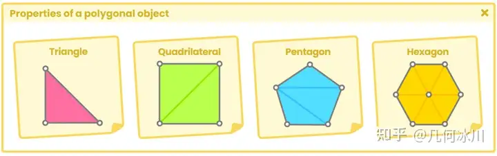
Fig. 1.0.1a
基本体(primitive) 是由多边形构成的三维几何对象,在诸如Unity、Maya、Blender等不同的开发软件中用作预定义对象。最常见的基本体有球体、正方体、四边形、圆柱体和胶囊体等。这些物体虽然形状各异,但属性相似:它们都有顶点、切线、法线、UV 坐标和颜色,这些属性被存储在一种名为 “ 网格(mesh) “的数据类型中。
我们可以在着色器中独立访问所有这些属性,并将它们保存在向量中(例如 float4 pos: POSITION [n])。这样做的好处是我们可以修改它们的值,从而编写出令人兴奋的效果。为了更好地理解这一概念,我们将给出关于多边形物体属性的定义。
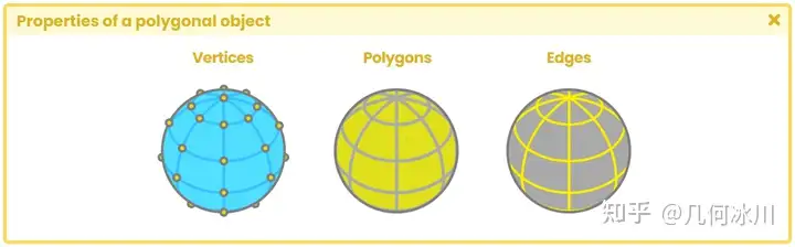
Fig. 1.0.1b
1.0.2 | 顶点
1.0.3 | 法线
1.0.4 | 切线
1.0.5 | UV坐标
1.0.6 | 顶点颜色
1.0.7 | 渲染管线架构
1.0.8 | 应用阶段
1.0.9 | 几何处理阶段
1.1.0 | 光栅化阶段
1.1.1 | 像素处理阶段
1.1.2 | 渲染管线类型
1.1.3 | 前向渲染
1.1.4 | 延迟渲染
1.1.5 | 我该用哪种渲染管线?
1.1.6 | 矩阵与坐标系统
Unity中的Shader
2.0.1 | 什么是着色器(shader)?
2.0.2 | 编程语言介绍
2.0.3 | 着色器的种类
2.0.4 | 标准表面着色器
2.0.5 | 无光照着色器
2.0.6 | 屏幕特效着色器
2.0.7 | 计算着色器
2.0.8 | 光线追踪着色器
属性、命令与函数
3.0.1 | 顶点/片元着色器的结构
3.0.2 | ShaderLab着色器
3.0.3 | ShaderLab的属性
3.0.4 | 数字与滑条类型
3.0.5 | 颜色与向量类型
3.0.6 | 纹理类型
3.0.7 | 自定义材质属性绘制器
3.0.8 | MPD开关
3.0.9 | MPD关键词枚举
3.1.0 | MPD枚举
3.1.1 | MPD指数滑条与整数范围
3.1.2 | MPD空白与标题
3.1.3 | ShaderLab子着色器
3.1.4 | ShaderLab标签
3.1.5 | 队列标签
3.1.6 | 渲染类型标签
3.1.7 | SubShader混合
原文
Blending is the process of mixing two pixels into one. Its command is compatible with both *Built-in RP* and *Scriptable RP* . *Blending* occurs in a stage called " **merging** " which combines the final color of a pixel (those pixels that have been processed in the fragment shader stage) with its depth. This stage, which occurs at the end of the render pipeline; after the **fragment shader stage** , is where the stencil-buffer, z-buffer and color blending are executed. By default, this property is not written in our shader since it is an optional function and is used mainly when we work with transparent objects, e.g., when we must draw a pixel with a low opacity level in front of another. Its default value is "Blend Off", but we can activate it to generate different types of Blending, like those that appear in photoshop. Its syntax is as follows: ```text Blend [SourceFactor] [DestinationFactor] ``` " **Blend** " is a function that requires two values called "factors" for its operation and based on an equation it will be the final color that we will obtain on-screen. According to the official documentation in Unity, the equation that defines the value of the Blending is as follows: > B = SrcFactor * SrcValue [OP] DstFactor * DstValue. To understand this operation, we must consider the following: The **fragment shader stage** occurs first and then, as an optional process; the **merging stage** . **"SrcValue"** (source value), which has been processed in the **fragment shader stage** , corresponds to the pixel’s RGB color output. **"DstValue"** (destination value) corresponds to the RGB color that has been written in the "destination buffer", better known as "render target" (SV_Target). When the Blending options are not active in our shader, SrcValue overwrites DstValue. However, if we activate this operation, both colors are mixed to get a new color, which overwrites the previous DstValue. **"SrcFactor"** (source factor) and "DstFactor" (destination factor) are vectors of three dimensions that vary depending on their configuration. Their main function is to modify the SrcValue and DstValue values to achieve interesting effects. Some factors that we can find in the Unity documentation are: * **Off** , disables Blending options. * **One** , (1, 1, 1). * **Zero** , (0, 0, 0). * **SrcColor** is equal to the RGB values of the SrcValue. * **SrcAlpha** is equal to the Alpha value of the SrcValue. * **OneMinusSrcColor** , 1 minus the RGB values of the SrcValue (1 - R, 1 - G, 1 - B). * **OneMinusSrcAlpha** , 1 minus the Alpha of SrcValue (1 - A, 1 - A, 1- A). * **DstColor** is equal to the RGB values of the DstValue. * **DstAlpha** is equal to the Alpha value of the DstValue. * **OneMinusDstColor** , 1 minus the RGB values of the DstValue (1 - R, 1 - G, 1 - B). * **OneMinusDstAlpha** , 1 minus the Alpha of the DstValue (1 - A, 1 - A, 1- A). It is worth mentioning that the Blending of the Alpha channel is carried out in the same way in which we process the RGB color of a pixel, but it is done in an independent process because it is not used frequently. Likewise, by not performing this process, the writing on the render target is optimized. Let's exemplify the above explanation as follows. Let's say we have an RGB color pixel with the values [0.5R, 0.45G, 0.35B]. This color has been processed by the ** fragment shader stage** , therefore it corresponds to the *DstValue* . Now, we multiply this value by the "*SrcFactor* **One** " which equals [1, 1, 1]. Every number multiplied by "1" results in the same value, therefore, the result between the *SrcFactor* and the *DstValue* is the same as its initial value. > B = **[0.5R, 0.45G, 0.35B]** [OP] DstFactor * DstValue. "OP" refers to the operation that we are going to perform. By default, it is set to "Add". > B = [0.5R, 0.45G, 0.35B] + DstFactor * DstValue. Once we have obtained the value of the first operation, it is overwritten by DstValue, therefore, is set to the same color [0.5R, 0.45G, 0.35B]. So, we will multiply this color by the "*DstFactor* **DstColor** ", which is equal to the current value we have in the *DstFactor* . > DstFactor [0.5R, 0.45G, 0.35B] * DstValue [0.5R, 0.45G, 0.35B] = [0.25R, 0.20G, 0.12B]. Finally, the output color for the pixel is. > B = [0.5R, 0.45G, 0.35B] + [0.25R, 0.20G, 0.12B]. > B = [0.75R, 0.65G, 0.47B] If we want to activate Blending in our shader, we must use the **Blend **command followed by **SrcFactor** and then **DstFactor** . Its syntax is the following: ```text Shader "InspectorPath/shaderName" { Properties { … } SubShader { Tags { "Queue"="Transparent" "RenderType"="Transparent" } Blend SrcAlpha OneMinusSrcAlpha } } ``` If we want to use Blending in our shader, it will be necessary to add and modify the * "Render Queue"* . As we already know, the default value of the *"Queue"* tag is *"Geometry"* , which means that our object will appear opaque. If we want our object to look transparent, then we must first change the *"Queue"* to *"Transparent"* and then add some kind of blending. The most common types of blending are the following: * **Blend SrcAlpha OneMinusSrcAlpha** Common transparent blending * **Blend One One** Additive blending color * **Blend OneMinusDstColor One** Mild additive blending color * **Blend DstColor Zero** Multiplicative blending color * **Blend DstColor SrcColor** Multiplicative blending x2 * **Blend SrcColor One** Blending overlay * **Blend OneMinusSrcColor One** Soft light blending * **Blend Zero OneMinusSrcColor** Negative color blending A different way to configure our Blending is through the dependency "UnityEngine.Rendering. BlendMode". This line of code allows us to change, from the inspector, the Blending of an object in the material. To set it up, first we must add the *"Toggle Enum"* to our properties and then declare both the SrcFactor and the DstFactor. Its syntax is as follows: ```text [Enum(UnityEngine.Rendering.BlendMode)] _SrcBlend ("Source Factor", Float) = 1 [Enum(UnityEngine.Rendering.BlendMode)] _DstBlend ("Destination Factor", Float) = 1 ``` ```text Shader "InspectorPath/shaderName" { Properties { [Enum(UnityEngine.Rendering.BlendMode)] _SrcBlend ("SrcFactor", Float) = 1 [Enum(UnityEngine.Rendering.BlendMode)] _DstBlend ("DstFactor", Float) = 1 } SubShader { Tags { "Queue"="Transparent" "RenderType"="Transparent" } Blend [_SrcBlend] [_DstBlend] } } ``` Blending options can be written in different fields: within the **SubShader** field or the **Pass** field, the position will depend on the number of passes and the final result that we need.混合(Blending)是将两个像素处理成一个的过程,是内置渲染管线(Built-in)与可编程渲染管线(SRP)都兼容的一种命令。
*混合 *发生在“ 合并(merging) ”的阶段,它将像素的最终颜色(在片元着色器阶段处理后的像素)与像素的深度结合在一起。这个阶段位于渲染管线的末端,在片元着色器阶段之后,是执行模版缓冲(stencil-buffer)、深度缓冲(z-buffer)和颜色混合(color blending)的地方。
混合属性不会被写在新建的默认着色器里,因为这是一个通常被使用在透明物体中的可选功能,比如说当我们必须在一个像素前绘制另一个不透明度较低的像素时。
混合的默认值是“Blend Off”(不开启混合),但我们可以通过设置它来实现不同类型的颜色混合效果,就像在 Photoshop 中的混合效果那样。
混合的语法如下所示:
1
Blend [SourceFactor] [DestinationFactor]
“ 混合 ”是一个函数,需要两个输入,经过一个计算公式得到屏幕上的最终颜色。根据 Unity 的官方文档,定义 混合结果的值的等式如下:
B = SrcFactor * SrcValue [OP] DstFactor * DstValue.
为了理解这个公式,我们需要记住这个顺序: 首先是 片元着色器阶段 ,然后是可选的 合并阶段 。
“SrcValue” (源颜色)代表的是经过片元着色器处理的像素的RGB值。
“DstValue” (目标颜色) 代表的是已经写入“目标缓冲”的像素的RGB值,目标缓冲更常见的名字是渲染目标(SV_Target)。当我们没有在着色器中设置混合选项时,源颜色会直接覆盖目标值。如果我们设置了混合,源颜色与目标颜色就会混合产生一个新的颜色,再覆盖先前的目标颜色。
“SrcFactor” (源系数) and “ DstFactor “ (目标系数) 都是一个三维向量,它们主要的功能是修改源颜色和目标颜色来实现有趣的效果。
我们能在Unity官方文档(ShaderLab 命令:Blend - Unity 手册)找到一些系数:
- Off , 禁用混合选项。
- One , (1, 1, 1)。
- Zero , (0, 0, 0)。
- SrcColor 等于源颜色的RGB值。
- SrcAlpha 等于源颜色的透明度。
- OneMinusSrcColor , 1 - 源颜色的RGB值 (1 - R, 1 - G, 1 - B)。
- OneMinusSrcAlpha , 1 - 源颜色的透明度 (1 - A, 1 - A, 1- A)。
- DstColor 等于目标颜色的RGB值。
- DstAlpha 等于目标颜色的透明度。
- OneMinusDstColor , 1 - 目标颜色的RGB值 (1 - R, 1 - G, 1 - B)。
- OneMinusDstAlpha , 1 - 目标颜色的透明度 (1 - A, 1 - A, 1- A)。
值得一提的是,透明度(Alpha)通道的混合与 RGB 颜色混合的方式相同,但由于不常用,所以是在一个独立的流程中完成的。如果不执行透明度混合,写入渲染目标上的过程也会得到优化。
让我们来理解理解上面的这段话。
假设我们现在有一个RGB值为 [0.5R, 0.45G, 0.35B] 的像素,已经经过片元着色器的处理,所以这个像素现在就是我们的源颜色。现在,我们把这个源颜色乘上系数“*SrcFactor * One ”(即 [1, 1, 1]),由于每个数字乘以 “1” 的结果都是它本身,因此,源系数和源颜色之间的结果就等于 [0.5R, 0.45G, 0.35B] 。
B = [0.5R, 0.45G, 0.35B] [OP] DstFactor * DstValue.
“OP”指的是我们要执行的操作,一般默认设为加法(Add),如下所示:
B = [0.5R, 0.45G, 0.35B] + DstFactor * DstValue.
到这一步之后,再来看看已经写入颜色缓冲中的目标颜色(假设为 [0.5R、0.45G、0.35B])。让我们将目标系数设置成“DstFactor DstColor ”,该系数等于当前目标颜色的 RGB 值,则有:
DstFactor [0.5R, 0.45G, 0.35B] * DstValue [0.5R, 0.45G, 0.35B] = [0.25R, 0.20G, 0.12B].
所以最后输出的像素颜色是:
B = [0.5R, 0.45G, 0.35B] + [0.25R, 0.20G, 0.12B]. B = [0.75R, 0.65G, 0.47B]
如果我们想要在着色器中开启混合,我们就需要使用到混合指令、源系数和 目标系数 ,语法如下所示:
1
2
3
4
5
6
7
8
9
Shader "InspectorPath/shaderName"
{
    Properties { … }
    SubShader
    {
        Tags { "Queue"="Transparent" "RenderType"="Transparent" }
        Blend SrcAlpha OneMinusSrcAlpha
    }
}
如果我们想在着色器里使用混合就必须添加和配置“ 渲染队列(Render Queue) ”。我们已经学习过默认的“ 队列(Queue) ”标签是“ 几何(Geometry) ”,代表我们的物体是不透明的。如果我们想要让物体看起来有透明的感觉,就需要把“队列”标签设置为“ 透明(Transparent) ”,再设置混合选项。
最常见的几种混合命令如下所示:
- Blend SrcAlpha OneMinusSrcAlpha 传统透明度混合
- Blend One One 加法
- Blend OneMinusDstColor One 软加法
- Blend DstColor Zero 乘法
- Blend DstColor SrcColor 2x 乘法
- Blend SrcColor One 叠加
- Blend OneMinusSrcColor One 柔光
- Blend Zero OneMinusSrcColor 反色
另一种配置混合的方式是通过“UnityEngine.Rendering. BlendMode”,它允许我们从检查器中更改材质的混合效果。但首先,我们必须在属性中添加 “ Toggle Enum “,然后声明源系数和目标系数。
语法如下所示:
1
2
3
4
[Enum(UnityEngine.Rendering.BlendMode)]
    _SrcBlend ("Source Factor", Float) = 1
[Enum(UnityEngine.Rendering.BlendMode)]
    _DstBlend ("Destination Factor", Float) = 1
1
2
3
4
5
6
7
8
9
10
11
12
13
14
15
Shader "InspectorPath/shaderName"
{
    Properties
    {
        [Enum(UnityEngine.Rendering.BlendMode)]
        _SrcBlend ("SrcFactor", Float) = 1
        [Enum(UnityEngine.Rendering.BlendMode)]
        _DstBlend ("DstFactor", Float) = 1
    }
    SubShader
    {
        Tags { "Queue"="Transparent" "RenderType"="Transparent" }
        Blend [_SrcBlend] [_DstBlend]
    }
}
混合选项可以写在子着色器或** Pass** 语义块中,具体写在哪里取决于 pass 的数量和我们最终想要取得的结果。
3.1.8 | SubShader透明度遮罩
3.1.9 | SubShader颜色遮罩
3.2.0 | SubShader剔除与深度测试
3.2.1 | ShaderLab剔除
3.2.2 | ShaderLab深度写入
原文
This command controls the writing of the surface pixels of an object to the Z-Buffer, that is, it allows us to ignore or respect the depth distance between the camera and an object. ZWrite has two values, which are: On and Off, where "On" corresponds to its default value. We generally use this command when working with transparencies, e.g., when we activate the Blending options. * **ZWrite Off** For transparency. * **ZWrite On** Default value. Why should we disable the Z-Buffer when working with transparencies? Mainly because of the translucent pixel overlay (Z-fighting). When we work with semi-transparent objects, it is common that the GPU does not know which object lies in front of another, producing an overlapping effect between pixels when we move the camera in the scene. To fix this problem, we must simply deactivate the Z-Buffer by turning the **ZWrite** command to " **Off** " as the following example shows: ```text Shader "InspectorPath/shaderName" { Properties { … } SubShader { Tags { "Queue"="Transparent" "RenderType"="Transparent" } Blend SrcAlpha OneMinusSrcAlpha ZWrite Off } } ``` The Z-fighting occurs when we have two or more objects at the same distance from the camera, causing identical values in the Z-Buffer. 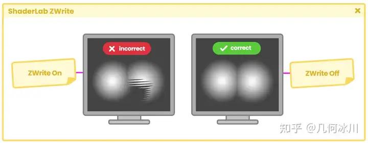 Fig. 3.2.2a This effect occurs when trying to render a pixel at the end of the rendering pipeline. Since the Z-Buffer cannot determine which element is behind the other, it produces flickering lines that change shape depending on the camera's position. To correct this issue, we simply need to disable the Z-Buffer using the "ZWrite off" command.深度写入这个命令控制了物体表面像素写入 Z 缓冲(深度缓冲)的这一过程。它允许我们忽略或写入物体与相机间的深度。深度写入有两个可以设置的值,分别是开启(On)和关闭(Off),默认值为开启。我们通常在处理透明度时(例如混合)会关闭深度写入。
- ZWrite Off 处理透明度时
- ZWrite On 默认值
为什么我们需要在处理透明度时禁用 Z 缓冲?主要是因为半透明像素叠加(深度冲突)的问题。当我们处理半透明物体时,GPU 通常不知道哪个物体位于另一个物体前面,因此当我们在场景中移动摄像机时,像素之间会产生奇怪的重叠效果。要解决这个问题,我们只需将深度写入命令设置为“ 关闭(Off) ”,停用 Z 缓冲区即可:
1
2
3
4
5
6
7
8
9
10
Shader "InspectorPath/shaderName"
{
    Properties { … }
    SubShader
    {
        Tags { "Queue"="Transparent" "RenderType"="Transparent" }
        Blend SrcAlpha OneMinusSrcAlpha
        ZWrite Off
    }
}
深度冲突(Z-fighting)发生在两个或多个物体具有相同的深度时,导致 Z 缓冲中的值完全相同。
https://picx.zhimg.com/80/v2-f16fe9a84f37cb76f4808e66cb3c24e8.png

Fig. 3.2.2a
接着,当尝试在渲染管线末端渲染这些像素时,就会出现上图所示的这种效果。由于 Z 缓冲无法确定究竟哪个物体位于另一个物体的后面,就会产生这些闪烁的线条。线条的形状会根据摄像机的位置而改变。
想修复这个问题,我们只需要用命令关闭深度写入(ZWrite off)、禁用 Z 缓冲区即可。
3.2.3 | ShaderLab深度测试
原文
ZTest controls how Depth Testing should be performed and is generally used in multi-pass shaders to generate differences in colors and depths. This property has seven different values, which are: * **Less.** * **Greater.** * **LEqual.** * **GEqual.** * **Equal.** * **NotEqual.** * **Always.** Which they correspond to a comparison operation. **ZTest Less** : (<) Draws the objects in front. It ignores objects that are at the same distance or behind the shader object. **ZTest Greater** : (>) Draws the objects behind. It does not draw objects that are at the same distance or in front of the shader object. **ZTest LEqual:** (≤) Default value. Draws the objects that are in front of or at the same distance. It does not draw objects behind the shader object. **ZTest GEqual** : (≥) Draws the objects behind or at the same distance. Does not draw objects in front of the shader object. **ZTest Equal** : (==) Draws objects that are at the same distance. Does not draw objects in front of or behind the shader object. **ZTest NotEqual** : (! =) Draws objects that are not at the same distance. Does not draw objects that are the same distance from the shader object. **ZTest Always** : Draws all pixels, regardless of the distance of the objects relative to the camera. To understand this command, we will do the following exercise: Let's suppose we have two objects in our scene; a Cube and a Sphere. The Sphere is in front of the Cube relative to the camera, and the pixel depth is as expected. 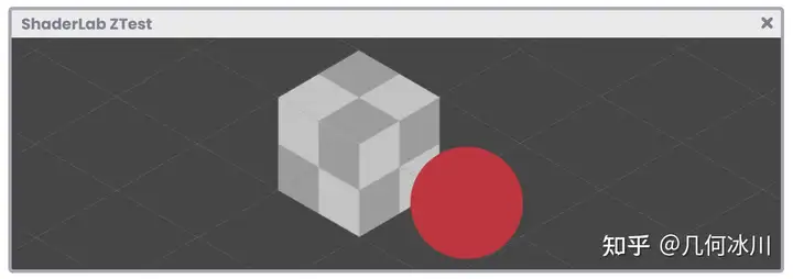 Fig. 3.2.3a If we position the Sphere behind the Cube then again, the depth values will be as expected, why? Because the **Z-Buffer** is storing depth values for each pixel on the screen. The depth values are calculated concerning the proximity of an object to the camera. 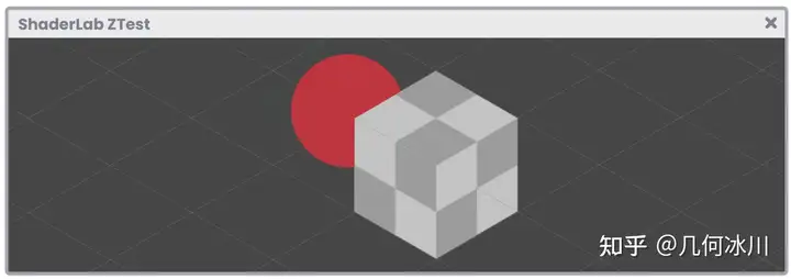 Fig. 3.2.3b Now, what would happen if we activated ZTest Always? In this case, Depth Testing would not be done, therefore, all pixels would appear at the same depth on screen. 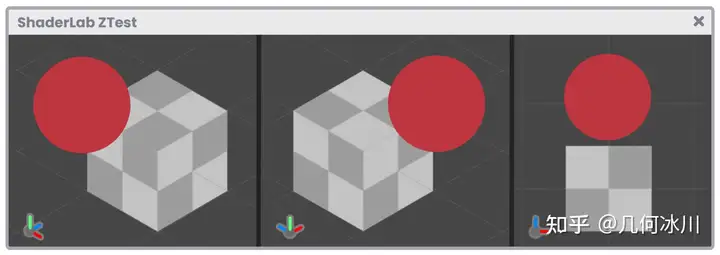 Fig. 3.2.3c Its syntax is the following: ```text Shader "InspectorPath/shaderName" { Properties { … } SubShader { Tags { "Queue"="Transparent" "RenderType"="Transparent" } ZTest LEqual } } ```深度测试(ZTest)通常用于在有多 pass 的着色器中生成颜色和深度差异。该属性有七个不同的值,分别是:
- Less.
- Greater.
- LEqual.
- GEqual.
- Equal.
- NotEqual.
- Always.
它们与比较操作相对应。
ZTest Less : (<) 绘制位于现有几何体前面的几何体。不绘制位于现有几何体相同距离或后面的几何体。
ZTest Greater : (>) 绘制位于现有几何体后面的几何体。不绘制位于现有几何体相同距离或前面的几何体。
ZTest LEqual: (≤) 默认值。绘制位于现有几何体前面或相同距离的几何体。不绘制位于现有几何体后面的几何体。
ZTest GEqual : (≥) 绘制位于现有几何体后面或相同距离的几何体。不绘制位于现有几何体前面的几何体。
ZTest Equal : (==) 绘制位于现有几何体相同距离的几何体。不绘制位于现有几何体前面的或后面的几何体。
ZTest NotEqual : (! =) 绘制不位于现有几何体相同距离的几何体。不绘制位于现有几何体相同距离的几何体。
ZTest Always : 不进行深度测试。绘制所有几何体,无论距离如何。
为了理解深度测试,我们将做以下练习: 假设场景中有两个物体(一个立方体和一个球体),相对于摄像机而言球体位于立方体的前方,像素深度符合预期。
https://picx.zhimg.com/80/v2-931e73ae4283caf9412196eaf837b81f.png

Fig. 3.2.3a
如果我们将球体放置在立方体后面,深度值也和我们预期的一样,为什么呢?因为** Z 缓冲**存储的是屏幕上每个像素的深度值,深度值是根据物体与相机之间的深度距离计算得出的。
https://picx.zhimg.com/80/v2-6fd2325002b2b6e0ee9147786b789b31.png

Fig. 3.2.3b
现在,如果我们将深度测试设置成“总是(Always)”会发生什么呢?在这种情况下,深度测试并不会发生,所有像素在屏幕上显示的深度是相同的。
https://picx.zhimg.com/80/v2-18f4d71f1a5a95de290e65bcf96155c5.png

Fig. 3.2.3c
深度测试的语法如下所示:
1
2
3
4
5
6
7
8
9
Shader "InspectorPath/shaderName"
{
    Properties { … }
    SubShader
    {
        Tags { "Queue"="Transparent" "RenderType"="Transparent" }
        ZTest LEqual
    }
}
3.2.4 | ShaderLab模板
3.2.5 | ShaderLab Pass
3.2.6 | CGPROGRAM/ENDCG
3.2.7 | 数据类型
3.2.8 | Cg/HLSL编程
3.2.9 | Cg/HLSL Include
3.3.0 | Cg/HLSL顶点输入&输出
3.3.1 | Cg/HLSL变量与连接向量
3.3.2 | Cg/HLSL顶点着色器
3.3.3 | Cg/HLSL片元着色器
3.3.4 | ShaderLab回退
其他概念与实现
4.0.1 | 着色器和材质的关系,好有一比啊~
4.0.2 | 我们的第一个Cg/HLSL着色器
4.0.3 | 为Cg/HLSL着色器加上透明度
4.0.4 | HLSL函数的结构
4.0.5 | Shader Debug
4.0.6 | 添加URP兼容
4.0.7 | 内置函数
4.0.8 | Abs函数
4.0.9 | Ceil函数
4.1.0 | Clamp函数
4.1.1 | Sin与Cos函数
4.1.2 | Tan函数
4.1.3 | Exp、Exp2与Pow函数
4.1.4 | Floor函数
4.1.5 | Step与SmoothStep函数
4.1.6 | Length函数
4.1.7 | Frac函数
4.1.8 | Lerp函数
4.1.9 | Min与Max函数
4.2.0 | 时间与动画
第二章 | 光照、阴影与表面
章节介绍
5.0.1 | 配置输入与输出
5.0.2 | 向量
5.0.3 | 点乘
5.0.4 | 叉乘
表面
6.0.1 | 法线贴图
6.0.2 | DXT压缩
6.0.3 | TBN矩阵
光照
7.0.1 | 光照模型
7.0.2 | 环境光颜色
7.0.3 | 漫反射
7.0.4 | 镜面反射
原文
One of the most common reflection models in computer graphics is the Phong model (Bui Tuong Phong), which adds specular brightness to a surface according to its normal. In fact, in Maya 3D there is a material with this name and its precise function is to generate shiny surfaces. Fig. 7.0.4a According to its author, to add specular reflection, you must carry out the following operation: Note that this equation is very similar to the function that allows us to calculate diffuse reflection. The big difference lies in the calculation of the vector [h] which corresponds to a half vector called “halfway”. This allows us to appreciate the brightness of the reflection when it is close to [n]; where the latter corresponds to the surface normals. To understand the concept, we will begin our study by demonstrating specular reflection, assuming we have a flat surface and directional light pointing towards it as follows: Fig. 7.0.4b From the image above, we can deduce that specular reflection has the same angle as the light direction. This represents a problem given that if our eye/camera is not in the same direction of reflection, then we will not be able to see it. To solve this, we can calculate an intermediate vector between the normals and the light direction, following the view direction. Fig. 7.0.4c The vector [e] corresponds to the “view direction”, while the vector [h] is the halfway value that we have calculated between the light direction and the surface normal. To determine the value of the vector [h] we can perform the following function. It is worth mentioning that for our program we are going to use normalized vectors, this means that their magnitude will equal “one”, therefore, the previous operation can be reduced to the following function: In the reflection calculation, there will be at least three variables that we will have to add in our code, these correspond to lighting direction surface normals the halfway value that includes the view direction Additionally, if we want to add specular maps, we will have to calculate the reflection color. We will start a new program to review these concepts, for this, we will create an Unlit Shader which we will call USB_specular_reflection. It is worth mentioning that many of the operations that we will perform in this section are the same as those carried out in USB_diffuse_shading, so we can start from scratch or continue from the shader that we developed in the previous section. Within our program, we will create a function called “SpecularShading.” Within it, we will include the properties mentioned above as follows: // internal structure of the SpecularShading function float3 SpecularShading ( float3 colorRefl, // Sa float specularInt, // Sp float3 normal, // n float3 lightDir, // l float3 viewDir, // e float specularPow // exponent ) { float3 h = normalize(lightDir + viewDir); // halfway return colorRefl* specularInt * pow(max(0, dot(normal, h)), specularPow); } On this occasion, we have declared a function called SpecularShading that returns a three-dimensional vector for its RGB colors. Among its arguments we can find the reflection color (colorReflRGB), specular intensity (specularInt [0, 1]), surface normals (normal XYZ), light direction (lightDir XYZ), view direction (viewDir XYZ) and the specular exponent of (specularPow [1, 128]). In the same way that we did in the diffuse reflection calculation, the normals and the view and lighting directions will be calculated in world-space, therefore, some transformations will have to be made in the vertex shader stage. We will start by configuring three properties for our shader: a texture property for the specular map, a reflection intensity range between zero and one, and a new specular exponent range between 1 and 128. Unlike the _MainTex property, _SpecularTex has a black color as a default. This can be corroborated in the definition “black” found at the end of the statement. Its operation is quite simple: If we do not assign a texture from the Unity Inspector, then the object will look black. Note that specular is going to be added to the main texture, therefore, for this case black will not be visible graphically because, as we already know, black equals “zero”, and zero plus one equals one. Fig. 7.0.4d Next, we must declare the connection variables for the three properties that we have added. Why have we discarded the variable _SpecularTex_ST in the above example? As we already know, the connection variables ending in the suffix _ST add tiling and offset to their texture. In the case of _SpecularTex it will not be necessary to add this type of transformation because, generally, textures or specular maps do not need them due to their consistent nature. Another connection variable that we have generated is _LightColor[n]. This variable will be used to multiply the color result of _SpecularTex, in this way, the specular color will be affected by the color of the light source that we have in our scene. The properties are now functional, so we can start implementing the SpecularShading function in the fragment shader stage. We will start by calculating the reflection color. The first argument in the SpecularShading function corresponds to reflection color. To do this, we multiply the texture _SpecularTex by the lighting color (colorRefl), and the factor is stored within a three-dimensional vector called specCol, which is assigned as the first argument. The second argument corresponds to specular intensity, for this, we can simply assign the property _SpecularInt, which is a range between zero and one [0, 1]. The third argument in the function refers to the object normals in world-space. To do this, we have to add the normals in both the vertex input and output and then transform their space into the vertex shader stage, in the same way we did in the diffuse reflection calculation. We will start by configuring the normals in the vertex input. Then we must assign the normals in the vertex output, however, we must remember that the NORMAL semantic does not exist for this process, therefore, we must use TEXCOORD[n] as it has up to four dimensions. Before returning to the fragment shader stage, we create one last property in the vertex output. This property will be used later in the calculation of the view direction, as a reference point. As we can see, a new property called vertex_world has been included, which refers to the position of the object vertices in world-space. We then go to the vertex shader stage to transform the coordinates’ space, however, unlike the previous processes, we now use the UnityObjectToWorldNormal function to transform the normals from object-space to world-space. UnityCg.cginc includes the UnityObjectToWorldNormal function, which is equivalent to inversely multiplying the unity_ObjectToWorld matrix by the object normal input. Next we can look at its internal structure. One factor to consider is that normal_world is normalizing the transformation operation. This is because normals are a direction of space; a three-dimensional vector returning a maximum magnitude of “one”, while vertex_world remains a position in space, with the difference now being calculated in world-space. We will continue with the SpecularShading function. fixed4 frag (v2f i) : SV_Target { fixed4 col = tex2D(_MainTex, i.uv); // we implement the normals in world-space float3 normal = i.normal_world; fixed3 colorRefl= _LightColor0.rgb; fixed3 specCol = tex2D(_SpecularTex, i.uv) * colorRefl; half3 specular = SpecularShading(specCol, _SpecularInt, normal, 0, 0, 0); return col; } As we can see, a new three-dimensional vector called normal has been created. This vector has its normal output in world-space, that’s why it has been assigned as the third argument in the function. It will not be necessary to generate any kind of lighting transformation because we can use the internal variable _WorldSpaceLightPos[n], which refers to the light direction in worldspace. fixed4 frag (v2f i) : SV_Target { fixed4 col = tex2D(_MainTex, i.uv); // let’s calculate the light direction float3 lightDir = normalize(_WorldSpaceLightPos0.xyz); float3 normal = i.normal_world; fixed3 colorRefl= _LightColor0.rgb; fixed3 specCol = tex2D(_SpecularTex, i.uv) * colorRefl; half3 specular = SpecularShading(specCol, _SpecularInt, normal, lightDir, 0, 0); return col; } Now we only need to calculate the view direction since the last argument in the SpecularShading function corresponds to the exponential value (specularPow) which increases or decreases reflection. To calculate the view direction, we must subtract the object vertices in world-space from the camera also in world-space. Unity has an internal variable called _WorldSpaceCameraPos, which gives us precise access to the scene’s camera position. fixed4 frag (v2f i) : SV_Target { fixed4 col = tex2D(_MainTex, i.uv); // let’s calculate the light direction float3 viewDir = normalize(_WorldSpaceCameraPos - i.vertex_world); float3 lightDir = normalize(_WorldSpaceLightPos0.xyz); float3 normal = i.normal_world; fixed3 colorRefl= _LightColor0.rgb; fixed3 specCol = tex2D(_SpecularTex, i.uv) * colorRefl; // we pass the view direction to the function half3 specular = SpecularShading(specCol, _SpecularInt, normal, lightDir, viewDir, _SpecularPow); return col; } The only operation left is to add specularity to the main texture, to do this we perform the following operation: fixed4 frag (v2f i) : SV_Target { fixed4 col = tex2D(_MainTex, i.uv); float3 viewDir = normalize(_WorldSpaceCameraPos - i.vertex_world); float3 lightDir = normalize(_WorldSpaceLightPos0.xyz); half3 normal = i.normal_world; fixed3 colorRefl= _LightColor0.rgb; fixed3 specCol = tex2D(_SpecularTex, i.uv) * colorRefl; half3 specular = SpecularShading(specCol, _SpecularInt, normal, lightDir, viewDir, _SpecularPow); // let’s add the specularity to the texture col.rgb += specular; return col; } Remember that we cannot add a four-dimensional vector to a three-dimensional vector, so we must make sure that specular reflection is only added to the main texture RGB channels. By the fact that specular reflection is a lighting pass, we must once again go to the Tags and configure the render path in the same way as we did for diffuse reflection.计算机图形学中,最常用的一种反射模型是由 裴祥风(Bui Tuong Phong) 发明的 Phong 模型,该模型根据模型的法线实现了镜面反射。在 Maya 3D 中有一种材质就叫这个名字,可以为模型产生闪亮的表面。
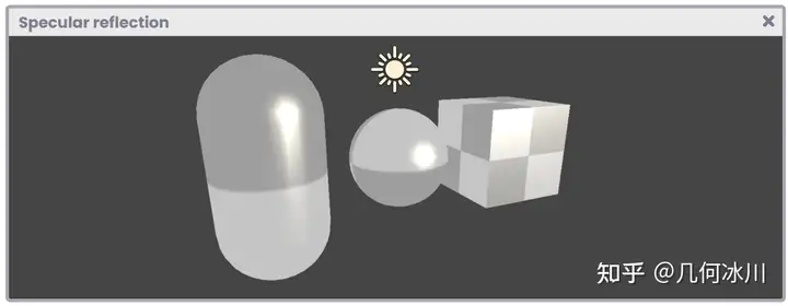
Fig. 7.0.4a
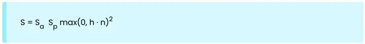
我们可以通过下述等式实现 Phong 模型的镜面反射:
https://picx.zhimg.com/80/v2-52f5711a52419941a465d4fdf832a3d4.png
注意看,这个等式非常像我们在上一小节中学习的兰伯特漫反射公式:
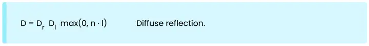
https://pica.zhimg.com/80/v2-eef0e6edcf308ceb265b49b2fa40547a.png
公式中的 [h] 指的是“半程向量”,当它越模型表面的法线 [n] 时,代表反射的亮度越亮。
为了理解这个概念,让我们从模拟镜面反射开始。假设现在我们有一个平面和一束打到平面上的平行光:
https://pic1.zhimg.com/80/v2-839b49f025250fbc6afa123468d17a60.png
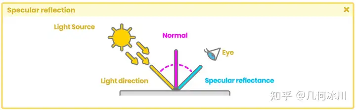
Fig. 7.0.4b
根据上图中的结果,结合初中物理所学的知识,我们可以推断出入射角与反射角的角度相同。这个性质带来了一个问题:如果我们的眼睛(相机)不在反射光的方向上,我们就无法看到它。为了解决这个问题,我们可以根据观察方向,计算出法线和光源入射方向之间的一个中间向量:
https://picx.zhimg.com/80/v2-6ebbe874a3cfe8c99a7a1a1e2098a164.png
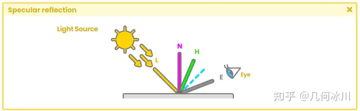
Fig. 7.0.4c
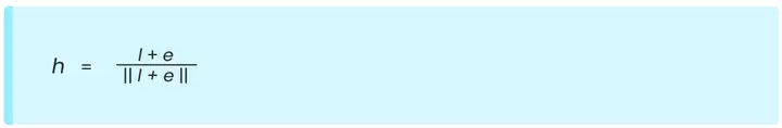
向量 [e] 指的是人眼(相机)的“观察方向”,向量 [h] 即法线和光源入射方向之间的“半程向量”。我们可以通过下面的公式计算半程向量 [h]:
https://pica.zhimg.com/80/v2-4c2f7b14ad966815d9ee64a39c1de9f5.png
值得一提的是,我们的程序中需要使用归一化后的向量,这代表向量的大小为“1”。因此,上述公式可以写作:
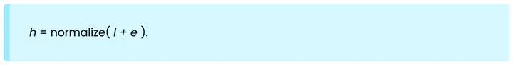
https://pica.zhimg.com/80/v2-ffa8862b9e55d5568ccf90360d7777ba.png
在反射的计算中,我们需要用到至少三个变量,分别是:
- 光照方向
- 表面法线
- 半程向量(包含了视线方向)
另外,如果我们想要加上高光贴图,我们将会需要计算反射颜色。
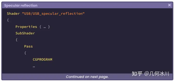
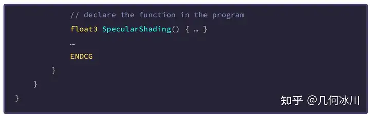
让我们创建一个名为 USB_specular_reflection 的 无光照着色器 。值得一提的是,这个着色器中的许多操作与上一小节中的 **USB_diffuse_shading **着色器是一样的,因此我们可以从头开始编写,也可以继续使用上一节中的着色器。
在程序中,让我们创建一个名为 SpecularShading 的函数,包含了我们在前文中提到的几个属性:
https://picx.zhimg.com/80/v2-e77448556e23bd83d19e42661b7a2cdb.png
https://picx.zhimg.com/80/v2-f17fee8a9e2305332e4fe3110a352c0f.png
1
2
3
4
5
6
7
8
9
10
11
12
13
14
15
// internal structure of the SpecularShading function
float3 SpecularShading
(
    float3 colorRefl, // Sa,镜面反射颜色
    float specularInt, // Sp,镜面反射系数
    float3 normal, // n,模型表面法线
    float3 lightDir, // l,光线角度
    float3 viewDir, // e,观察角度
    float specularPow // exponent,指数
)
{
    float3 h = normalize(lightDir + viewDir); // 半程向量

    return colorRefl* specularInt * pow(max(0, dot(normal, h)), specularPow);
}
在上面的代码中,我们声明了一个名为 SpecularShading 的函数,该函数返回一个包含 RGB 颜色的三维向量。在它的参数中,我们可以找到反射光颜色(colorReflRGB)、镜面反射强度(specularInt [0, 1])、模型表面法线(normal XYZ)、光照方向(lightDir XYZ)、观察方向(viewDir XYZ)和镜面反射指数(specularPow [1, 128])。
就像我们在上一小节中所做的那样,我们需要使用世界空间下的模型法线、观察方向和光照方向,因此需要在顶点着色器阶段完成一些变换操作。
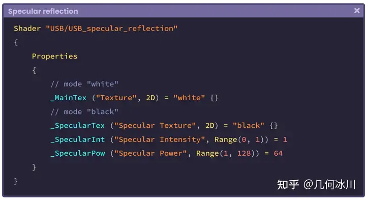
让我们在着色器中配置三个属性:纹理类型的高光贴图、[0, 1] 范围的镜面反射强度和 [1, 128] 范围的镜面反射指数:
https://pic1.zhimg.com/80/v2-52258fd709021e435a339a9e639eb411.png
与 _MainTex 属性不同的是,_SpecularTex 的默认值是黑色,这一点可以从语句末尾的“black”中得到印证。如果我们不从 Unity 检查器中指定纹理,那么模型看起来就会是黑色的。
请注意,镜面反射将被加到主纹理中,因此在这种情况下,黑色在图形上是不可见的,因为黑色等于“0”,而 0 + 1 = 1。
https://pica.zhimg.com/80/v2-bf529d79d7c0482b9d3ea83f2d84b544.png
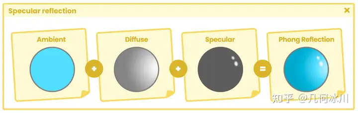
Fig. 7.0.4d
接下来,我们需要声明三个属性的连接变量:
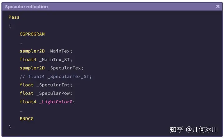
https://pica.zhimg.com/80/v2-f3be529609594b2f14947de4665e99ad.png
为什么我们在上面的代码中注释掉了 _SpecularTex_ST ?我们已经学习过,连接变量末尾的“ _ST ”为纹理加上了平铺和偏移,而一般来说,高光贴图** _SpecularTex** 不需要这两种变换。
我们还写了一个名为 _LightColor[n] 的连接变量,改变量将与 _SpecularTex 的颜色相乘,这样镜面反射的颜色就会被场景中的光源颜色所影响了。
现在属性们已经准备好了,我们可以开始在片元着色器中使用 **SpecularShading **函数了。让我们从计算反射光颜色开始:
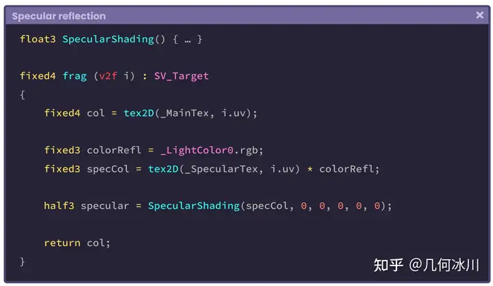
https://pic1.zhimg.com/80/v2-bb40396b828d9e2899a21a3390eb6e96.png
SpecularShading 函数的第一个参数代表了反射光颜色(Sa)。我们将高光贴图 _SpecularTex 与光源颜色(colorRefl)相乘,并将结果储存到名为 specCol 的三维向量中,传入函数的第一个参数。
第二个参数代表反射强度,我们可以直接使用属性 _SpecularInt ,范围为 [0, 1]:
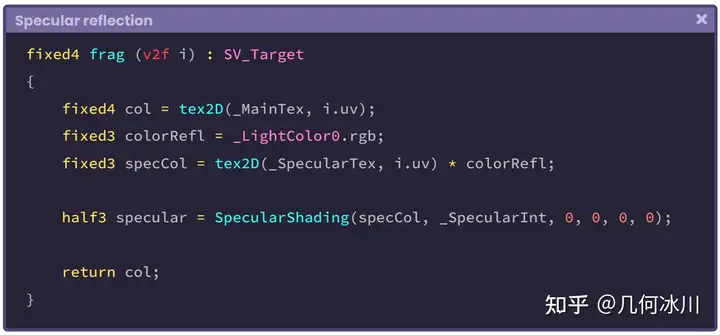
https://pica.zhimg.com/80/v2-56bd0b34850e8f5a5dcfac361e38e520.png
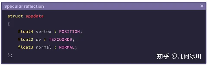
函数的第三个参数代表世界空间下的模型法线。我们需要将法线同时加入顶点输入与顶点输出中,并在顶点着色器阶段将法线变换到世界空间,这和我们在上一小节中所做的步骤相同。
让我们从配置顶点输入开始:
https://pic1.zhimg.com/80/v2-e458286735c4aa0b5e4371299a33f4b7.png
接着,我们需要在顶点输出中配置法线。然而,顶点输出结构体并不包含 NORMAL 语义,因此我们需要为法线配置四维语义 TEXCOORD[n]:
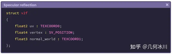
https://pic1.zhimg.com/80/v2-2cc8325dd946c3d13c1213380ec1ae87.png
在回到片元着色器之前,我们还需要在顶点输出中配置最后一项输出,该属性将被用于计算观察方向的参考点。
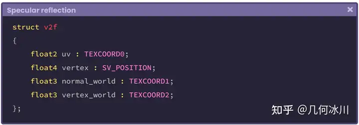
https://pic1.zhimg.com/80/v2-64814ac9952d8c2dc3d200786be5300e.png
如上述代码所示,我们添加了一个名为 vertex_world 的新属性,代表了模型顶点在世界空间中的位置。
接着,我们来到顶点着色器中,对顶点与法线进行变换。与之前不同的是,我们现在直接使用 UnityObjectToWorldNormal 函数直接将法线从模型空间变换到世界空间:
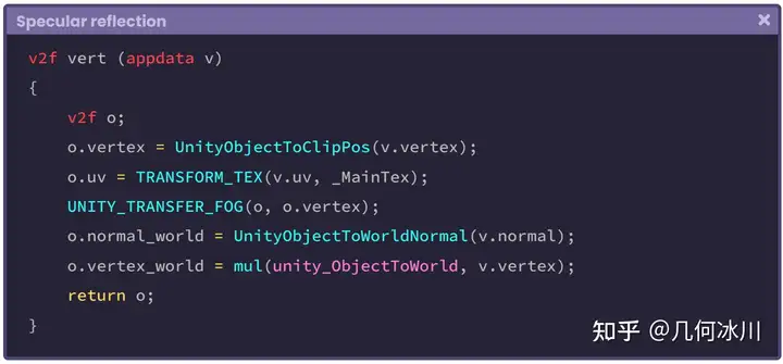
https://picx.zhimg.com/80/v2-07c6c25f4eaf4eb61ae4185cd28da1dd.png
UnityObjectToWorldNormal 函数被包含在 UnityCg.cginc 中,与将 _ObjectToWorld 矩阵与模型法线相乘的结果一致。让我们看看这个函数的内部结构(译者注:这里的norm不是范数,就是normal的简写):
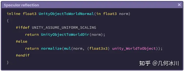
https://pica.zhimg.com/80/v2-695c6f0a4dd05305e57f06c363582431.png
需要注意的一点是,函数对 normal_world 进行了归一化处理,因此现在法线是一个大小为“1”的三维向量,代表世界空间中的一个方向。而 vertex_world 世界空间中的一个点(位置)。
让我们回到 SpecularShading 函数:
1
2
3
4
5
6
7
8
9
10
11
12
13
fixed4 frag (v2f i) : SV_Target
{
    fixed4 col = tex2D(_MainTex, i.uv);

    // 我们已经将法线变换到了世界空间
    float3 normal = i.normal_world;
    fixed3 colorRefl= _LightColor0.rgb;
    fixed3 specCol = tex2D(_SpecularTex, i.uv) * colorRefl;

    half3 specular = SpecularShading(specCol, _SpecularInt, normal, 0, 0, 0);

    return col;
}
我们可以看到,在片元着色器中我们创建了一个名为 normal 的新三维向量,获取了顶点输出中变换到了世界空间的法线。接着,我们将其传入到 SpecularShading 函数中作为第三个参数。
因为我们可以直接使用内部变量 _WorldSpaceLightPos[n] 来表示 *世界空间 *中的光照方向,因此不需要对光线进行任何变换。
1
2
3
4
5
6
7
8
9
10
11
12
13
14
fixed4 frag (v2f i) : SV_Target
{
    fixed4 col = tex2D(_MainTex, i.uv);

    // 让我们来计算光线方向
    float3 lightDir = normalize(_WorldSpaceLightPos0.xyz);
    float3 normal = i.normal_world;
    fixed3 colorRefl= _LightColor0.rgb;
    fixed3 specCol = tex2D(_SpecularTex, i.uv) * colorRefl;

    half3 specular = SpecularShading(specCol, _SpecularInt, normal, lightDir, 0, 0);

    return col;
}
现在我们只需要计算观察方向就好了,因为 SpecularShading 函数的最后一个参数对应镜面反射指数(specularPow),用于增加或减少反射。
为了计算观察方向,我们需要用世界空间下的相机位置减去世界空间下的模型顶点。Unity 提供了一个名为 _WorldSpaceCameraPos 的内置变量,这样我们就能精确地获取世界空间下的相机位置。
1
2
3
4
5
6
7
8
9
10
11
12
13
14
15
16
fixed4 frag (v2f i) : SV_Target
{
    fixed4 col = tex2D(_MainTex, i.uv);

    // 让我们来计算光线方向
    float3 viewDir = normalize(_WorldSpaceCameraPos - i.vertex_world);
    float3 lightDir = normalize(_WorldSpaceLightPos0.xyz);
    float3 normal = i.normal_world;
    fixed3 colorRefl= _LightColor0.rgb;
    fixed3 specCol = tex2D(_SpecularTex, i.uv) * colorRefl;

    // 将观察方向传入函数
    half3 specular = SpecularShading(specCol, _SpecularInt, normal, lightDir, viewDir, _SpecularPow);

    return col;
}
最后一步是将函数计算得到的镜面反射结果添加到主纹理上:
1
2
3
4
5
6
7
8
9
10
11
12
13
14
15
16
17
fixed4 frag (v2f i) : SV_Target
{
    fixed4 col = tex2D(_MainTex, i.uv);

    float3 viewDir = normalize(_WorldSpaceCameraPos - i.vertex_world);
    float3 lightDir = normalize(_WorldSpaceLightPos0.xyz);
    half3 normal = i.normal_world;
    fixed3 colorRefl= _LightColor0.rgb;
    fixed3 specCol = tex2D(_SpecularTex, i.uv) * colorRefl;

    half3 specular = SpecularShading(specCol, _SpecularInt, normal, lightDir, viewDir, _SpecularPow);

    // 让我们将镜面反射加到纹理上
    col.rgb += specular;

    return col;
}
请记住,我们不能直接将一个四维向量与一个三维向量相加,所以我们需要确保只将镜面反射结果加到了主纹理的 RGB 通道上。
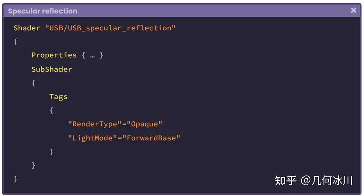
由于镜面反射是一种光照传递,我们必须再次进入 标签(Tags) 语义块,以配置漫反射的方式配置渲染路径:
7.0.5 | 环境反射
原文
7.0.6 | 菲涅尔效应
原文
The Fresnel effect (after its creator Augustin Jean Fresnel), also known as the Rim effect, is a type of reflection where its size is proportional to the incidence angle; the angle between the object normals and the camera direction. Fig. 7.0.6a The further the surface is from the camera, the more Fresnel reflection there will be because the angle between the incidence value and the object normals is greater. Fig. 7.0.6b When the angle between the incidence value and the normals equals “zero” degrees there is no reflection, because both vectors are parallel, on the other hand, when the angle equals “ninety” degrees, the reflection is full, and the vectors are perpendicular. This is quite interesting because, when the reflection is null, our program must return black. On the contrary, when it is full, it returns white, why? Because these correspond to the maximum and minimum illumination values of a pixel. To understand this concept, we must analyze the following function coming from the Fresnel Effect node in the Shader Graph. In the previous function several things are happening that we will detail throughout this section, for now, we will only focus on the output’s internal operation. This operation can be divided into three processes: This operation determines the angle between the incidence vector and the object normals, and as a result, returns a numerical range between “zero and one” [0.0f, 1.0f]. As we already know, the “dot” function will return “one, zero or minus one” depending on the angle between its arguments [-1.0f, 1.0f]. Since the reflection operation requires only a value between “zero and one,” the intrinsic function saturate has been added, limiting the values between this range. // it only can return "0" as minimum and "1" as maximum float saturate (float x) { return max(0, min(1, x)); } // it can modify the minimum and maximum range float clamp (float x, float a, float b) { return max(a, min(b, x)); } Saturate fulfills the same function as clamp, with the difference that with the latter we can modify the minimum and maximum value to generate the limit. Let’s continue with the operation “1 - x”. To understand its nature, we must return to the previous exercise. Dot product will return “one” [1] when the view direction vector and the normals are parallel and point in the same direction. This is a problem for us, because we need the operation to return “zero” [0] which is equivalent to black. Fig. 7.0.6c The operation “1 - x” has the function of flipping the result as follows. // if the normals and the view are parallel in the same direction saturare(dot(float3(0, 1, 0), float3(0, 1, 0))) = 1 1 - 1 = 0 // if the normals and the view are perpendicular saturare(dot(float3(0, 1, 0), float3(1, 0, 0))) = 0 1 - 0 = 1 Finally, in the function, we can find the operation “pow( x,power )” which allows us to increase or decrease the range of reflection. To understand in detail the Fresnel operation of Shader Graph, we will start a new Unlit Shader that we will call USB_fresnel_effect. The first thing we must do is to include this function within our program. It should be noted that the function unity_FresnelEffect_float is a “void” type. In section 4.0.4 of Chapter I, we reviewed the difference between implementing an empty function and one that returns a value. In this case, we have to declare some variables and pass them as arguments, as appropriate. We will start by declaring the function in the fragment shader stage. void unity_FresnelEffect_float() { … } fixed4 frag (v2f i) : SV_Target { fixed4 col = tex2D(_MainTex, i.uv); // initialize the void function unity_FresnelEffect_float(0, 0, 0, 0); return col; } The first argument in the function corresponds to the object normals in world-space, so we have to go to vertex input and use NORMAL semantics, and then transform its space coordinates in the vertex shader stage. Due to the fact that we use the normals in the fragment shader stage, we have to declare a vector in the vertex output, this way we can store the result of the transformation. // vertex input struct appdata { float4 vertex : POSITION; float2 uv : TEXCOORD0; float3 normal : NORMAL; }; // vertex output struct v2f { float4 vertex : SV_POSITION; float2 uv : TEXCOORD0; float3 normal_world : TEXCOORD1; float3 vertex_world : TEXCOORD2; }; The vector vertex_world has been added to the vertex output because we need this variable to calculate the view direction. If we pay attention, we will notice that the process is exactly the same as we have done in previous sections for the reflection calculation. To continue with the implementation of the Fresnel function, we will return to the fragment shader stage and declare two vectors: one for the normals calculation and the other for the view direction. fixed4 frag (v2f i) : SV_Target { fixed4 col = tex2D(_MainTex, i.uv); float3 normal = i.normal_world; float3 viewDir = normalize(_WorldSpaceCameraPos - i.vertex_world); // assign the normals and view direction to the function unity_FresnelEffect_float(normal, viewDir, 0, 0); return col; } In the example above, a three-dimensional vector called normal has been declared to store the normals output value in world-space. Then a new vector called viewDir has been declared which contains the view direction calculation. Both vectors have been assigned as the first and second arguments in the function unity_FresnelEffect_float, since they are required in its internal operation. For the third argument (fresnel power) we have to declare a property with a numerical range. This will be used to modify the reflection range. We will use the property _FresnelPow as a third argument in the function, as an exponential value; while we will use _FresnelInt to increase or decrease the amount of Fresnel effect in the object. As we already know, we must declare connection variables for both properties within our program. Once this process is done, the property will be connected to our program, this means that we can dynamically modify the reflection range from the Unity Inspector. Now we can use _FresnelPow as the third argument in the function. fixed4 frag (v2f i) : SV_Target { fixed4 col = tex2D(_MainTex, i.uv); float3 normal = i.normal_world; float3 viewDir = normalize(_WorldSpaceCameraPos - i.vertex_world); // add the exponent value in the function unity_FresnelEffect_float(normal, viewDir, _FresnelPow, 0); return col; } The fourth corresponds to the function output value, where we will save the color output. To do this, we simply create and add a floating variable to the function. fixed4 frag (v2f i) : SV_Target { fixed4 col = tex2D(_MainTex, i.uv); float3 normal = i.normal_world; float3 viewDir = normalize(_WorldSpaceCameraPos - i.vertex_world); // initialize the color output in black float fresnel = 0; // add the output color unity_FresnelEffect_float(normal, viewDir, _FresnelPow, fresnel); col += fresnel *_FresnelInt; return col; } In the previous example, a variable called fresnel was declared, which was initialized at “zero” (black). It was then included in the function as the fourth argument, as output. This means that within this variable is the result of the final operation that occurs in the unity_ FresnelEffect_float function. At the end of the operation, we can see that the fresnel variable result, due to its intensity (_FresnelInt), was added to the base texture color called “col”. This adds reflection to the object in our scene and also allows us to modify its intensity value.菲涅尔(Fresnel) 效应(由奥古斯丁-让·菲涅耳发现)也被称为边缘效应(Rim effect),是一种反射,其大小与物体法线与相机方向的夹角成正比。
https://pic1.zhimg.com/80/v2-39bce8e1195abe3adbafe644b83d3a81.png
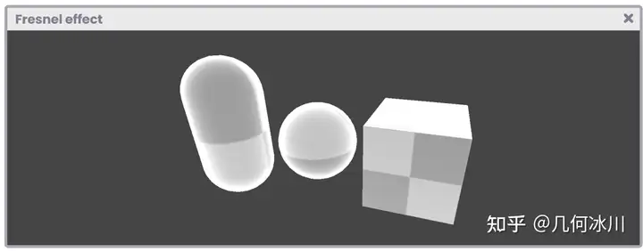
Fig. 7.0.6a
模型表面距离相机越远,菲涅尔反射就越多,因为入射方向(相机)与物体法线之间的角度越大。
https://pica.zhimg.com/80/v2-c15465cdeaed6503f3ae91966d7f0414.png
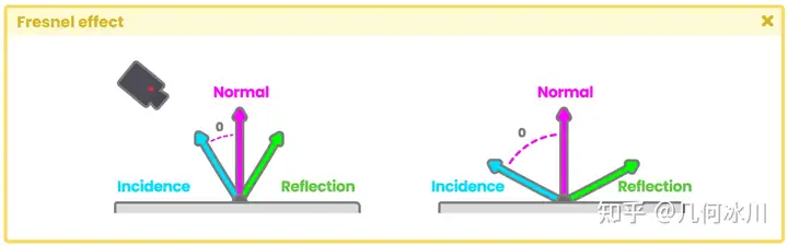
Fig. 7.0.6b
当入射方向(相机)与法线之间的夹角为“0°”时没有反射存在,因为两个向量是平行的。当入射方向与法线之间的夹角为“90°”时全反射,两个向量相互垂直。这非常有趣,因为当没有反射时函数返回黑色,全反射时则返回白色,这些值对应于像素的最大和最小光照值。
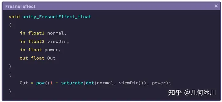
为了理解这个概念,我们需要分析来自 Shader Graph 中的 Fresnel Effect 节点函数。
https://picx.zhimg.com/80/v2-d14eb54f66b1aff3564dded4a19a4220.png
在这个函数中发生了一些事情,我们将在本节中进行详细介绍,现在我们暂时先只关注输出的内部操作。这一操作可分为三个过程:

https://picx.zhimg.com/80/v2-2905ed31bdb07dc0431eaea74bd3d5ce.png
这个操作将确定入射方向与模型法线之间的夹角,并返回范围在 0 ~ 1([0.0f, 1.0f])之间的数。
我们已经知道,“点乘(dot)”函数根据夹角的值将返回计算结果。由于反射操作只需要一个介于“0”和“1”之间的值,因此我们添加了函数 saturate ,以限制这个范围之间的值。
1
2
3
4
5
6
7
8
9
10
11
// 最小返回“0”,最大返回“1”
float saturate (float x)
{
    return max(0, min(1, x));
}

// 允许设置最小值与最大值的区间
float clamp (float x, float a, float b)
{
    return max(a, min(b, x));
}
Saturate 函数与 clamp 函数功能类似,不同之处在于后者可以修改最小值和最大值来控制范围。
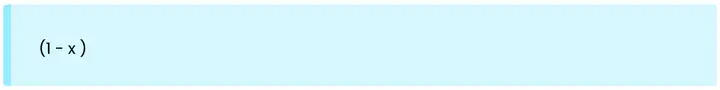
让我们从“1 - x”继续。
https://picx.zhimg.com/80/v2-0cd7962d39abeae670d26dfa15128c27.png
要理解这个操作的本质,我们必须回到之前的练习。当视线方向和表面法线平行且指向同一方向时,点乘将返回 “1”。这对我们来说是个问题,因为我们需要该操作返回“0”,也就是黑色。
https://pic1.zhimg.com/80/v2-47b1394cf780133a1ba87f5e6ebbaf7f.png
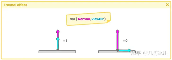
Fig. 7.0.6c
而“1 - x”运算具有如下翻转结果的功能:
1
2
3
4
5
6
7
// 如果法线和视线方向在同一方向上平行
saturare(dot(float3(0, 1, 0), float3(0, 1, 0))) = 1
1 - 1 = 0

// 如果法线和视线方向垂直
saturare(dot(float3(0, 1, 0), float3(1, 0, 0))) = 0
1 - 0 = 1
最后,在函数中,我们可以找到“ pow(x, power) ”运算。该运算允许我们增加或减少反射的范围。
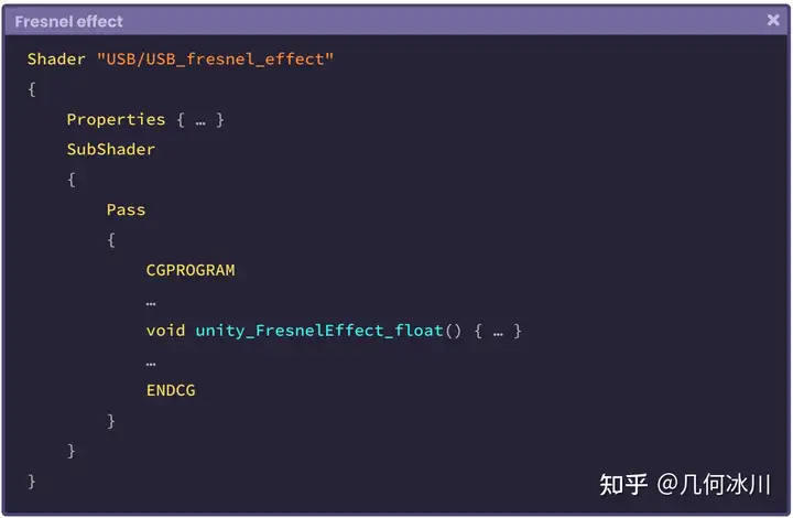
让我们创建一个名为 USB_fresnel_effect 的无光照着色器帮助我们更好的了解 Shader Graph 中的 Fresnel 节点中的操作。让我们在着色器中加入以下代码:
https://picx.zhimg.com/80/v2-a7a581d0ce31405771910ef1f5c9bdaf.png
需要注意的是,函数 unity_FresnelEffect_float 的返回类型是“ void ”,在第 4.0.4 小节中我们曾学习了无返回值和有返回值的函数的区别。在上述的代码中,我们声明了一些变量,并将它们作为参数传入函数中。
让我们在片元着色器中声明该函数。
1
2
3
4
5
6
7
8
9
10
11
void unity_FresnelEffect_float() { … }

fixed4 frag (v2f i) : SV_Target
{
    fixed4 col = tex2D(_MainTex, i.uv);

    // 初始化无返回值函数
    unity_FresnelEffect_float(0, 0, 0, 0);

    return col;
}
函数的第一个参数代表了物体在世界空间的法线,所以我们需要在顶点输入的结构体中使用 NORMAL 语义,并在顶点着色器阶段变换法线的坐标空间。
由于我们需要在片元着色器中使用法线,因此需要在顶点输出结构体中声明一个向量用以存储变换后的法线。
1
2
3
4
5
6
7
8
9
10
11
12
13
14
15
16
// 顶点输入
struct appdata
{
    float4 vertex : POSITION;
    float2 uv : TEXCOORD0;
    float3 normal : NORMAL;
};

// 顶点输出
struct v2f
{
    float4 vertex : SV_POSITION;
    float2 uv : TEXCOORD0;
    float3 normal_world : TEXCOORD1;
    float3 vertex_world : TEXCOORD2;
};
顶点输出结构体中的向量 vertex_world 用于计算视线方向。
如果我们多加留心,就会发现上面的步骤和前面学习反射的小节中所演示的代码一致。
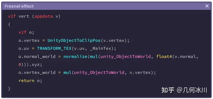
https://picx.zhimg.com/80/v2-15b6928809add885cf44f4e4a9ea95b6.png
现在让我们来到片元着色器中声明两个向量,一个代表法线、另一个代表视线方向。
1
2
3
4
5
6
7
8
9
10
11
12
fixed4 frag (v2f i) : SV_Target
{
    fixed4 col = tex2D(_MainTex, i.uv);

    float3 normal = i.normal_world;
    float3 viewDir = normalize(_WorldSpaceCameraPos - i.vertex_world);

    // 将法线与视线方向传入函数中
    unity_FresnelEffect_float(normal, viewDir, 0, 0);

    return col;
}
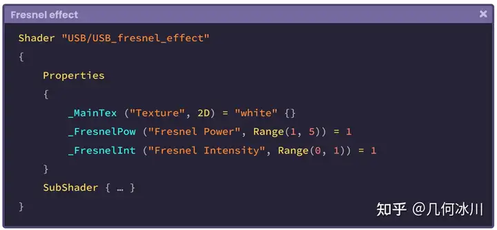
在上面的例子中,三维向量 normal 已经存储了世界空间的法线值;另一个三维向量 viewDir 则计算了视线方向,两个向量均作为参数传入 unity_FresnelEffect_float 函数中,并将在函数内的计算中被使用。第三个参数是“菲涅尔指数”,我们可以传入一个范围来控制反射的范围。
https://pica.zhimg.com/80/v2-74dd5a8c6c4ce39f3d2e17bc4052ec4d.png
我们将 _FresnelPow 属性作为函数的第三个参数。作为一个指数值,我们将使用 _FresnelInt 属性来增加或减少对象中的菲涅尔效应的量。接着,我们需要在程序中为这两个属性声明连接变量:
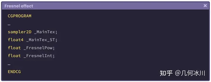
https://pica.zhimg.com/80/v2-06c7541796c7c267e35555b05d0136c3.png
这一步完成之后,属性与后续的着色器程序产生关联,我们就可以在 Unity 的检查其中动态修改它们了。现在,我们将 _FresnelPow 作为第三个参数传入函数中。
1
2
3
4
5
6
7
8
9
10
11
12
fixed4 frag (v2f i) : SV_Target
{
    fixed4 col = tex2D(_MainTex, i.uv);

    float3 normal = i.normal_world;
    float3 viewDir = normalize(_WorldSpaceCameraPos - i.vertex_world);

    // 将指数值传入函数中
    unity_FresnelEffect_float(normal, viewDir, _FresnelPow, 0);

    return col;
}
第四个参数对应的是函数输出值,我们将在这里保存颜色输出。为此,我们只需在函数中创建并添加一个浮点数类型的变量:
1
2
3
4
5
6
7
8
9
10
11
12
13
14
15
fixed4 frag (v2f i) : SV_Target
{
    fixed4 col = tex2D(_MainTex, i.uv);

    float3 normal = i.normal_world;
    float3 viewDir = normalize(_WorldSpaceCameraPos - i.vertex_world);
    // initialize the color output in black
    float fresnel = 0;

    // 添加输出颜色
    unity_FresnelEffect_float(normal, viewDir, _FresnelPow, fresnel);

    col += fresnel * _FresnelInt;
    return col;
}
在上面的例子中,我们声明了一个名为 fresnel 的变量并赋值为“0”(黑色),它作为第四个参数被传入函数中并作为其输出值,即 unity_ FresnelEffect_float 函数的最终运算结果。
完成编写后,我们就可以看到菲涅尔反射的效果了。由于其强度( _FresnelInt )已被添加到名为“col”的基本纹理颜色中,这样就为场景中的物体增加了反射效果,同时也允许我们修改其强度值。